Fluke 8050A Multimeter LCD Display Project
Fluke 8050A Multimeter LCD Display Project
This series of wiki pages attempts to document my project to replace the old monochromatic, 4-digit, 7-segment LCD numeric display with a 320x240 color TFT graphical display.
What?
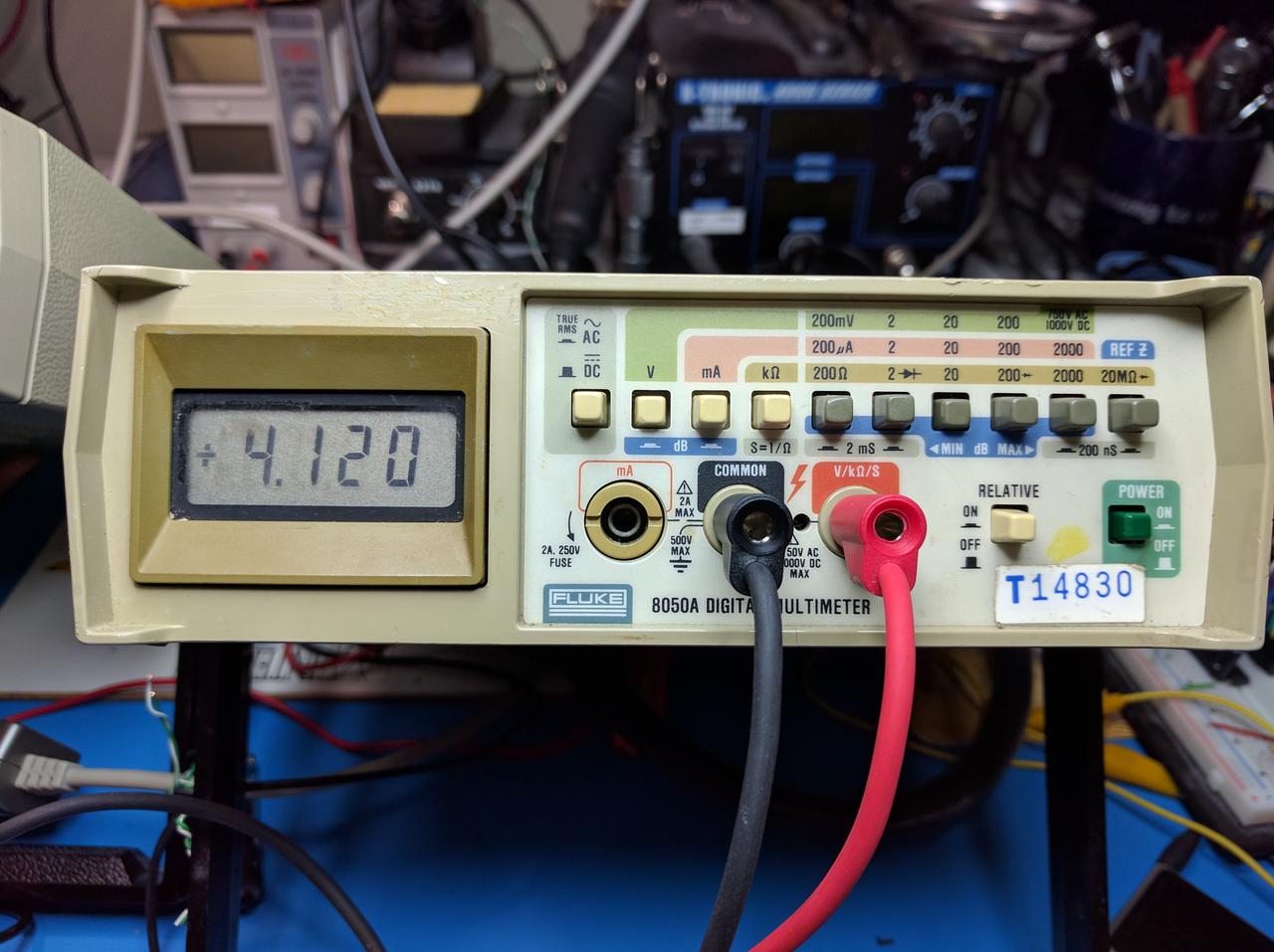
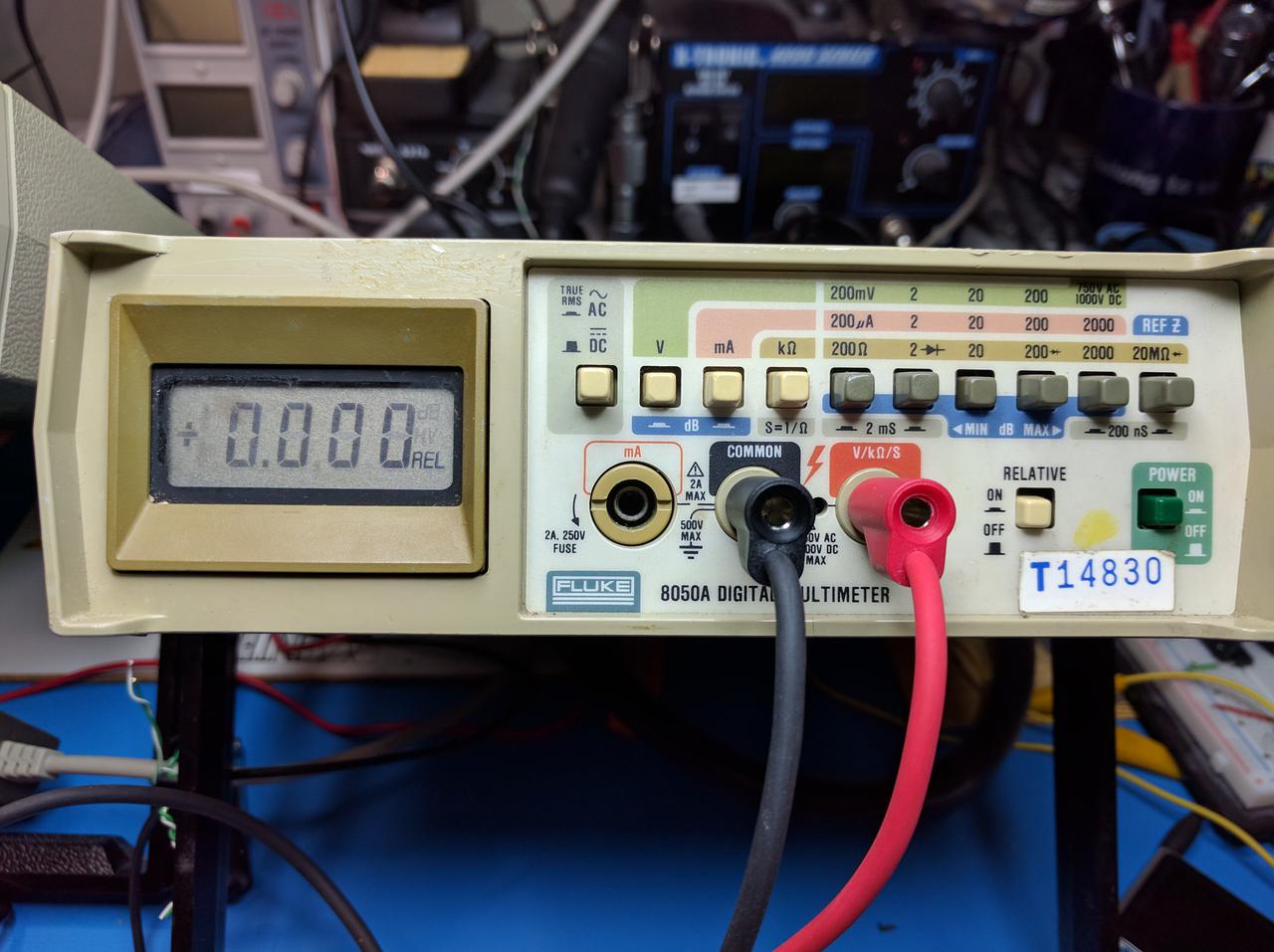
The outcome of the project is to replace and improve the display on the Fluke 8050A multimeter. The orginal display has a crude (at least these days) 4½ digit LCD display, with a few special function annunciators. It can be difficult to read; these photos have a very nearby light source illuminating them for. I wanted to turn something like this:
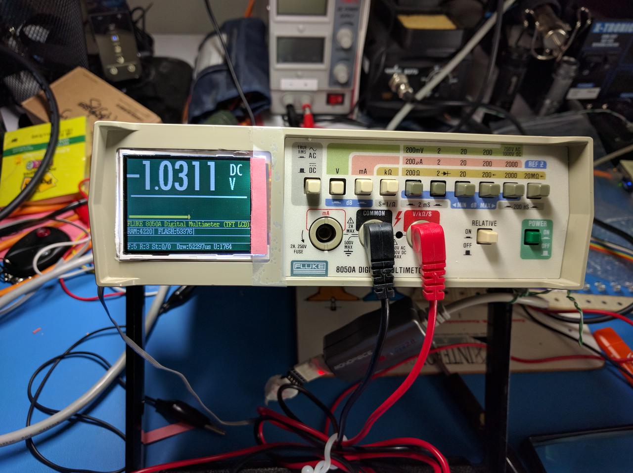
 into an improved display that looks like this:
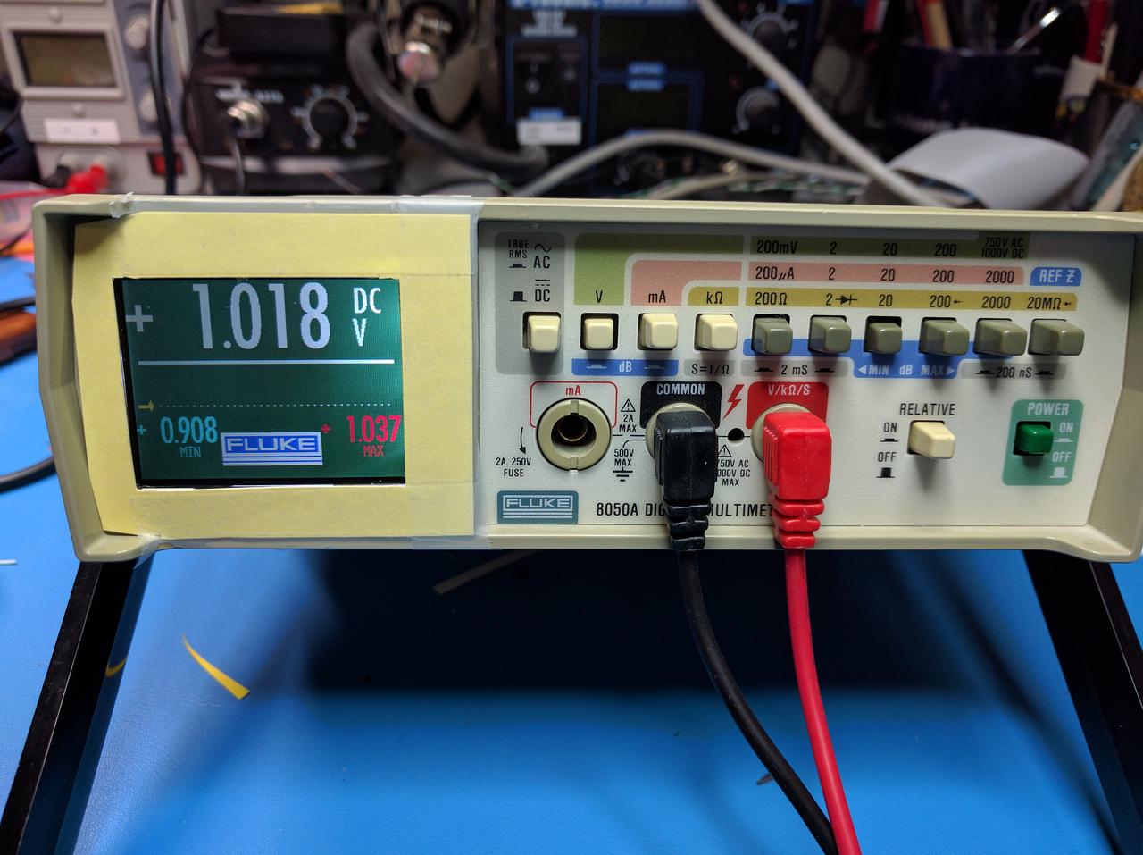
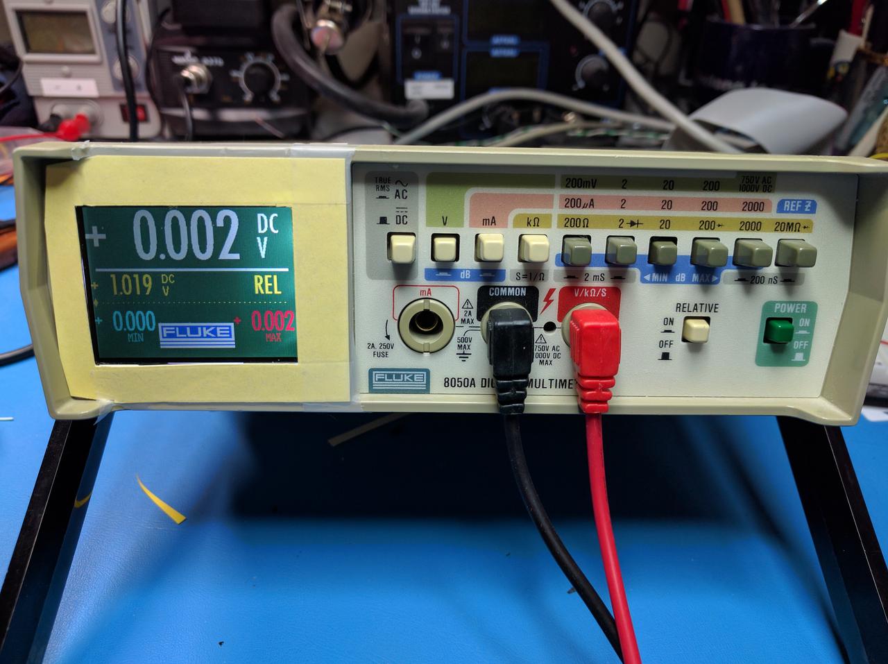
The display shows what measurement mode the multimeter is in (Ohms, Volts, milli-amps), if the meter is performing a DC measurement or an AC RMS measurement.
Minimum and maximum measurement values are also shown on the display. These min/max values are reset when the measurement mode or scale are changed, or if the meter is put into or out of "Relative" mode.
It also has an auxiliary display when in "relative" mode, where in addition to displaying the current relative offset, the absolute measurement used as the basis of the offset is displayed as a reminder.
The display has a distinctive flashing pattern when an over-range condition exists, and if the "High Voltage" state exists where the separator line changes color to red.
A horizontal bar-graph showing an "analog" representation of the value displayed from 0 to 2000 units exists below the display, and also shows fading pointers for the last 10 measurements in an attempt to show how a varying signal changes.
{{ projects:fluke8050a:2016-09-10_00.36.48.jpg?direct&200|}} When the Fluke 8050A is powered-up and has the REL button (Relative Display) depressed, additional debugging information is displayed. At power-on, an information screen is displayed with some free memory information, and other info as time goes on. In addition, while in this mode, if a character is received on USART1 at 115200 8N1, the start-up of the display "application" is aborted, and you can interact with the Forth interpreter to poke around. Just typing "display" will start it back up and continue until another character is received. Handy for debugging..
{{projects:fluke8050a:2016-09-10_00.37.16.jpg?direct&200|}}
When started in "debug" mode, additional information is then display while the multimeter is in use, including free memory, time in microseconds taken to update the display, number of display update cycles (which is rendered in reverse colors producing a blinking effect on every other update cycle.)
See the page for a much more detail look at the various meter displays.
Where?
Lots of info here on the wiki, also the code is pushed to GitHub for convienience.
How?
Rather than making this page an even larger wall of text, see these other pages for further detail on the actual implementation:
Why?
Why do such a thing?
-
Because it's there!
-
Because it's possible!
-
Just because you can do it, doesn't mean you should do it.
These are are things that I've thought to myself during this project.
Mostly, because I had a solution looking for a problem. I was looking for trouble, and managed to find just a little bit..
I had recently discovered very inexpensive ARM Cortex-M3 microcontroller boards available through the usual channels on eBay and other venues. Because of their low, low cost, I've accumulated a number of these things, with the intention of doing something clever with them.
I happened across stm32duino project, which ports the Arduino software environment over to the the ST micro STM32 line of microcontrollers. I thought this was a fairly wonderful thing, as these chips are just as cheap as the various Arduino platforms and much more performant than the ATMEL CPUs the Arduino used. I thought if I was going to invest the time getting to known a new CPU architecture, I might as well learn more about ARM and ARM Cortex-M0/M3/M4 CPUs. So I set upon playing around with all this, and developed a bit of a dislike for the Arduino IDE, having grown up over the last couple of decades with ''make'' and ''emacs'' and similar development tools.
At was also around this time that I had noticed a series of postings on JeeLabs on these same parts, and a port of FORTH to these devices. I had been quite a long time since I had played around with FORTH (on an old Z80 and later Amiga system) and thought that this was an interesting platform to experiment with.
And I owned a nice Fluke 8050A multimeter. However, even though my LCD display had not deteriorated like many others had, the lack of a backlight and marginal contrast made it a little difficult to use on my workbench. Doing some Google searches revealed a number of other projects to replace the display on this fine meter with 7-segment LED displays.. but I also saw a couple of other projects to replace them with a graphical LCD, which just happens to fit (barely) within the enclosure.
This was the final bit of rationalization to embark on this rather silly project. It was much more a learning experience than fixing an actual problem that I had. But I'd never let practicality stand in my way before.
Who?
To paraphrase.. because I can stand on the shoulders of others, I can see further than I could on my own. There are a great many people who have shared the work they've done with us, and I've learned and adopted ideas, techniques and tools from them. I hope you can in turn learn something from this work.
See list of credits and resources here.
Other Fluke 8050A Projects
I am hardly the first person who's wanted to improve their Fluke 8050A multimeter. There are a number of projects where the LCD display was replaced with a number of discrete 7-segment LED digits, but I didn't pursue this line of thought for my meter. In my case, the LCD was still fully functional, if only a bit difficult to read with the lighting situation on my workbench. I wasn't going to undertake a one-for-one replacement project where the considerable effort didn't really produce a significantly improved result.
This whole project formed in my mind when I somehow stumbled across this web site on the Internet Fluke8050A Hi Res Display and a pointer to it on Hackaday http://hackaday.com/2013/08/23/upgrading-a-fluke-multimeter-with-a-masterful-addition/ while, of course, looking for something else.
I was probably searching for a manual for my used Fluke 8050A multimeter, or perhaps seeing about fitting a backlight to the difficult to read LCD display. This whole concept really intrigued me! Essentially, "wiretapping" the display signals coming out of the CPU driving the display and generating a graphics display. The interesting piggy-back construction technique was also novel..
I wasn't a real PIC CPU fan, and didn't think investing my time replicating that project as-is would be fun, vs. some other microcontroller I would be more likely to use.. The author of this project graciously made the source code available, and it was a very helpful introduction to how the Fluke 8050A functioned and what was needed.
Subsequently, I found A new graphic display for a Fluke 8050A multimeter which document his effort for a similar solution. This implementation was based on an Arduino CPU (instead of the PIC) and with a bit more sophisticated display scheme. Source code was also available for this Atmel ATMEGA32U4 CPU used, and it was very well documented with additional valuable tidbits of information on how the Fluke 8050A multimeter functioned.
A novel approach here was to remove the Fluke's F8 CPU from its socket, and insert a piggyback board arrangement into the now empty socket, while then carrying the CPU on the piggyback board. This was a very non-invasive modification to the Fluke (in contrast to my thoughts of soldering some wires on the back side of the Fluke PCB on the CPU socket pins.
As it turns out, this was a great approach as I did my development on an "expendable" Fluke 8050A that I bought from an EBay seller that had some other issues. It worked well enough for my purposes, and I wouldn't feel bad if I smoked my $25 development platform. When done with development, it was a 10 minute effort to move the piggyback board to my working 8050A with no soldering required.
STM32 ARM Cortex-M3 resources
I have had a dangerous interest in little STM32 microcontrollers for some time. I thought that this type of platform would be a good foundation for all the little endless projects I had in mind (but somehow never get around to building..) I wasn't interested in getting invested in an Arduino-compatible bit of technology, because by now, the cost of 32-bit ARM microcontrollers is essentially the same as much less capable Atmel AVR series devices.
Previously I did some work on a project involving an STM32L103 device and Bluetooth Low Energy and spent some time with ChibiOS, a very nice and compact RTOS for microcontrollers, especially the STM32 devices with their suite of on-chip peripherals.
There is also some great work being done to bring the Arduino IDE and an Arduino compatible API to STM32 parts at Arduino for STM32, which I did play around with somewhat.
I thought that my Fluke 8050A project might use one or the other of these platforms, but..
Then I happened across a rather nice FORTH for Cortex-M3 based systems called Mecrisp Forth. It has in-built support for compiling words to either RAM or the STM32's Flash memory, being able to erase chunks of Flash within Forth and of course, interactive bare-metal access.
I also saw a series of articles on http://jeelabs.org, including Forth in 7 easy steps to get started, and then a comprehensive series of articles starting here and with a bunch of supporting material, including a complete (enough for my needs, anyway) set of code on github for a number of different CPU variations and peripherals.
Not being one to stick with the mainstream (as my NeXT and Amiga computers in the distant past might attest), I plunged ahead in this direction. Many years ago, I had a fascination with these small, but power embedded languages like Forth. Thanks to these other open source efforts, I had a wonderful head-start in this direction.